


Dry Electrode Making for Solid-State Battery
Mikrouna’s dry electrode technology presents a new approach. It includes high-speed mixing of the PTFE binder, active material, and conductive agent, subsequently pressing the mixture through the roller press machines. This semi-finished product is then laminated with a current collector foil coated with conductive adhesive to produce a dry electrode sheet. A notable advantage of this process is its minimal reliance on organic solvents, which is instrumental in enhancing the battery’s capacity and cycle life.
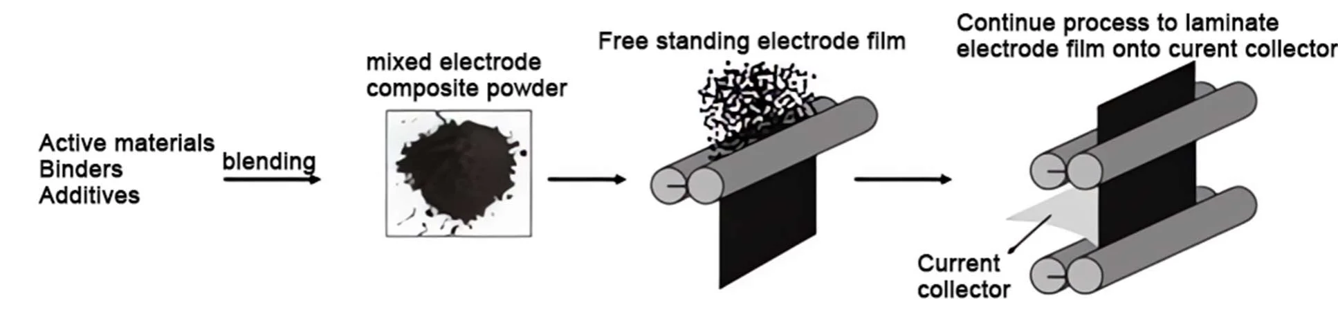
The transformation from dry electrode powder to dry electrode film encompasses three pivotal steps:
1. Compaction of Dry Electrode Powder: The dry electrode powder is pressed into a thin, semi-finished dry electrode film.
2. Rolling to Desired Thickness: This semi-finished film undergoes rolling to attain the specified thickness.
3. Lamination Process:
(1) Conductive Adhesive Coating: The current collector foil is coated with a layer of conductive adhesive.
(2) Lamination: The semi-finished dry electrode film is then laminated with the coated current collector foil to complete the dry electrode sheet.
Concept of Dry Electrode in Solid-State Batteries
A dry electrode represents a coating technology that does not rely on liquid solvents to disperse active materials and conductive additives. Instead, it directly blends active materials, conductive agents, and binders using solid powders and then applies this mixture onto a current collector (such as aluminum foil or copper foil) through pressing or other mechanical methods.
Compared to traditional wet coating techniques, the dry electrode process eliminates the use of solvents (such as NMP, N-methylpyrrolidone), thereby removing the need for solvent drying and recovery steps. This results in a simpler, faster, more economical, and environmentally friendly manufacturing process. Despite the significant advantages of dry electrode technology, its practical application in production still faces some challenges. For instance, ensuring uniform adhesion of the dry powder material onto the current collector and achieving large-scale production are ongoing issues. These problems are gradually being addressed through technological improvements and innovations.
Tesla’s Maxwell Dry Electrode employs a series of processes including dry mixing, fibrillation, granulation, film formation, thinning and compaction, and final lamination with the current collector.
(1) Dry Mixing: This initial step involves the mechanical mixing of active materials, conductive agents, and dry powder electrolytes to form a uniform dry powder mixture.
(2) Fibrillation: In this step, the binder is processed into a fibrous structure, making it easier to bind with other components in the dry state. This enhances the adhesive properties and mechanical strength of the mixture, similar to the liquid binding effect in wet processes.
(3) Granulation: The fibrillated mixture is then processed through mechanical granulation equipment to form granular particles. These particles exhibit good fluidity and handling characteristics, suitable for subsequent film formation steps.
(4) Film Formation: The granular material is passed through a multi-roller system, where it undergoes initial roller pressing to form a support film, followed by subsequent roller pressing for thinning and compaction to enhance electrode performance. This results in a stable electrode film with good compactibility, ensuring excellent electrical conductivity and mechanical strength.
(5) Thinning and Compaction: This step further reduces the thickness of the electrode film while increasing its density, thereby enhancing electrode performance. The electrode film should have a low porosity and be firmly attached to the substrate to prevent peeling or cracking.
(6) Lamination with Current Collector: In the final step, the dry electrode film is securely bonded to the current collector (such as copper foil or aluminum foil), ensuring good electronic conduction paths and mechanical stability.
The dry electrode process utilized in Tesla’s Maxwell technology offers several advantages, including a simpler manufacturing process, thicker electrodes, and the elimination of solvents. This unique dry forming process does not use any solvents, making it an environmentally friendly green process that saves materials, time, and labor costs. Additionally, the dry electrode process can significantly increase the packing density of the electrode, maximize the use of active materials, and thus enhance the energy density of the battery.
I. Analysis of Dry Electrode Preparation Technology
Introduction to Dry and Wet Processes and Material Comparison
The traditional wet process involves mixing active materials, conductive agents, and binders in a solvent in a specific proportion, and then applying the mixture to the surface of the current collector through a slit coating die and roller pressing it as required.
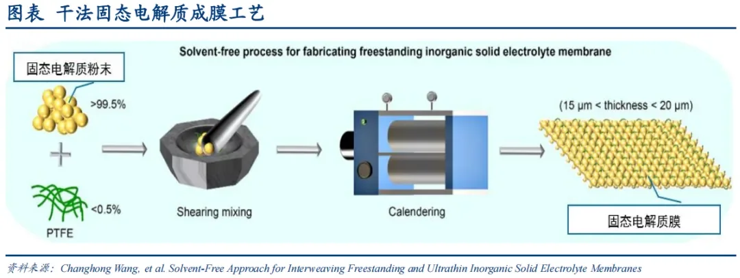
The dry process involves dry mixing active particles and conductive agents, then adding a binder to form a self-supporting membrane under the fibrillation action of the binder, and finally roller pressing it onto the surface of the current collector.
II. Comparison of Advantages and Disadvantages between Dry and Wet Electrodes
Lower Cost and Manufacturing Efficiency of Dry Process
The dry manufacturing process has fewer steps, and after mass production, the overall manufacturing cost of the battery cells can be reduced by 18%, equivalent to a decrease of 0.056 yuan/Wh. In the traditional wet process, coating, drying, and solvent recovery account for 22.76% and 53.99% of equipment, labor, factory cost, and energy cost respectively. The dry process replaces the slurry coating of the traditional wet process with the manufacturing of a self-supporting membrane, eliminating the need for NMP solvent and the electrode drying and solvent recovery steps, thereby achieving lower battery cell manufacturing costs.
The dry process is more environmentally friendly and more suitable for large-scale production. NMP (N-methylpyrrolidone) solvent is toxic and not environmentally friendly, and its recovery in the traditional wet process consumes a significant amount of energy. The dry process eliminates the need for solvents, simplifies the process by reducing drying and solvent recovery steps in electrode coating, requires less equipment space, and is more suitable for large-scale production of electrode sheets.
Increased Active Material Density and Energy Density of Dry Process
Under the fibrillation action of PTFE, dry electrodes achieve a smoother morphology compared to wet electrodes. Since wet processes require solvents, more gaps remain between active materials and conductive agents after solvent evaporation, resulting in lower compaction density of the material. In the dry process, there is no drying step, so there are no gaps left after solvent evaporation, and particle contacts are tighter.
Dry electrodes can achieve higher compaction density. After compaction under dry conditions, there are fewer cracks and micropores. The compaction density of lithium iron phosphate can be increased from 2.30 g/cm³ to 3.05 g/cm³, an increase of 32.61%; the compaction density of ternary materials can be increased from 3.34 g/cm³ to 3.62 g/cm³, an increase of 8.38%; and the compaction density of graphite anodes can be increased from 1.63 g/cm³ to 1.81 g/cm³, an increase of 11.04%. Due to the presence of more active materials per unit volume, dry electrodes also offer a technical pathway to achieve higher energy density.
Under the same conditions, the energy density of dry batteries can be increased by 20%. According to experimental data from Maxwell, the energy density of dry electrodes can exceed 300 Wh/kg and has the potential to reach 500 Wh/kg.
Dry electrodes have a larger thickness limit, allowing for increased areal capacity. The coating thickness limit of traditional wet electrodes is 160 µm, while the thickness range of dry electrodes is 30µm-5mm. This larger thickness range can accommodate a wider variety of active materials.
Superior Electrical Performance of Dry Batteries
The cycle performance, durability, and impedance of batteries produced using the dry process are superior under laboratory conditions. Since there is currently no industrial production data, this article cites public data from the paper “Preparation and Performance Study of Solvent-Free Dry Electrodes for Lithium-Ion Batteries”.
The fibrous network enhances the material stability of dry electrodes, thereby improving electrical performance. In wet processes, after 500 cycles, internal stress in active particles accumulates, leading to cracks in the cross-section and ultimately reducing battery performance. In the dry process, the fibrous network coats the surface of active materials, and after 500 cycles of charging and discharging, the network structure remains intact with fewer cracks on the particle surface. Meanwhile, the fibrillation network structure inhibits the volume expansion of active materials, prevents particles from detaching from the current collector, enhances stability, and improves electrical performance.
III. Dry Electrode Process Steps and Parameters for Solid-State Batteries
1. Dry Mixing
Purpose: To form a uniform dry powder mixture of active material (LiFePO4, NCM, NCA), conductive agent (Carbon black, Graphite), and solid electrolyte.
Key Parameters:
Particle Size Distribution: Typically 1-20 microns for cathode materials (e.g., NCM, LFP); ensure D90 using laser particle size analyzer.
Mixing Time and Speed: 10-30 minutes, with speed to be determined.
Bulk Density: 0.5-1.0 g/cm³, depending on active material type and mix ratio.
2. Binder Fibrillation and Mixing
Purpose: To process the binder into a fibrous structure for better adhesion and mechanical strength in the dry state.
Key Parameters:
Fiber Length and Diameter: 0.1-10 microns in length, 50-200 nanometers in diameter.
Fibrillation Time and Temperature: 5-15 minutes, 60-80°C, depending on binder properties.
Shear Rate: 100-1000 s⁻¹.
Uniformity: ±10% deviation in component distribution, verified by EDX or SEM.
3. Granulation
Purpose: To produce granular particles with good flowability and processing characteristics for subsequent film formation.
Key Parameters:
Particle Size and Shape: 50-500 microns, with sphericity 0.8-1.0 for uniform film formation and compaction.
Particle Density: 0.8-1.2 g/cm³.
4. Film Formation, Thinning, and Compaction
Purpose: To form a stable electrode film with good compaction, conductivity, and mechanical strength.
Film Formation Parameters:
Thickness: 50-200 microns, ±5% uniformity.
Porosity: 20-40%.
Thinning and Compaction Parameters:
Compaction Pressure: 100-200 MPa.
Compaction Speed: 1-20 m/min.
Thickness Reduction: 10-30%, depending on initial thickness and target density.
Final Thickness: 40-150 microns.
Porosity Reduction: 5-10%.
Compaction Density Increase: Up to 32.61% for LFP, 8.38% for NCM.
Thickness and Density Uniformity: ±5 microns and ±5% CV, respectively.
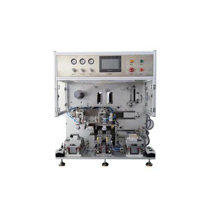
5. Lamination with Current Collector
Purpose: To securely bond the dry electrode film to the current collector for good electronic conduction and mechanical stability.
Key Parameters:
Lamination Temperature: 60-150°C, depending on binder type and current collector material.
Lamination Time: 1-5 minutes.
Roll Pressure: 10-100 MPa.
Contact Resistance: <1 mΩ·cm².
Peel Strength: ≥3 N/cm.
Adhesion Shear Strength: >1-3 MPa.
Current Collector Surface Treatment: Roughness Ra 0.5-2 microns, surface energy >30 mN/m.
This streamlined and translated version captures the essential process steps, purposes, and key parameters for the dry electrode process in solid-state battery manufacturing.
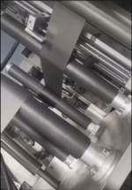
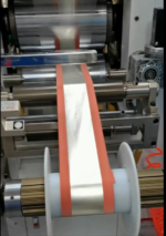
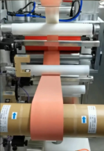
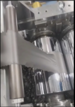
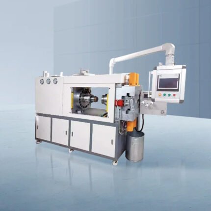
The trend of future development lies in the large-scale and integrated equipment. By integrating functions such as feeding, mixing, fiberization, membrane formation, rolling, slitting, and winding, the turnover time is reduced, and efficiency and consistency are improved, thereby enhancing the equipment’s value. The rolling part of the calendaring and trimming integrated machine used by Tesla resembles an open mill. After material is fed into the head of the machine, the mixture enters the rollers along the tape-feeding direction. Since the roller speed downstream is faster than upstream, the high shear force formed in the roller gap extrudes and mixes the active material, conductive agent, and binder. The self-supporting membrane formed under the action of fibrillation adheres to the faster downstream roller and undergoes repeated calendaring. The metering roller on the side of the machine controls the roller speed and temperature, while a slitting system is set up at the tail of the machine to cut the formed wide electrode film into narrow electrode films as required. The double-sided coating and current collector composite laminating machine integrates the production of positive/negative electrode films, the lamination of electrode films and current collectors, and the winding of electrode sheets. Essentially, it is a calendaring and trimming composite integrated machine.
The advantages of the calendaring and trimming integrated machine are:
(1) Improved production efficiency of dry electrodes;
(2) Reduced turnover time of electrode sheets between equipment, minimizing powder shedding;
(3) Better control over product yield and improved consistency;
(4) Enhanced ability to detect indicators such as electrode sheet thickness and calendaring uniformity;
(5) The double-sided coating and current collector composite laminating machine integrates the production of positive/negative electrode films, the lamination of electrode films and current collectors, and the winding of electrode sheets. Essentially, it is a calendaring and trimming composite integrated machine.
You must be logged in to post a review.
No PDF available for this product.
Reviews
Clear filtersThere are no reviews yet.