


Auto Degas Machine for Pouch Cell
Incoming battery size cell specifications:
| Name | Specification cell range | Schematic diagram of battery size |
| L2 | 160~300 mm | |
| W2 | 85~160°C | |
| L1 | 10~40°C | |
| W3 | 60~100 | |
| W1 | 5~15 mm | |
| T | 5~15 mm |
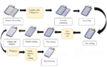
Main component mechanism:
| No. | Name of the institution | Description |
| 1 | Feeding mechanism
|
1. The positioning groove is convenient for discharging, and there is an inductor to sense whether there is a product in the feeding level.
2. Two sets of flat-head brass probes are used to test the voltage of the cell. 3. Both the top and bottom are equipped with scanning code guns for scanning code; 4. The voltage detection and scanning detection station detects that the battery is unqualified, will not be removed, and will eventually return to the feeding station. After the defective products are removed by hand, the sensor confirms that there is no material in the loading station before the new products can be put in.
|
| 2 | Battery positioning mechanism | 1. The battery table plate can be adjusted up and down, and has a flange to assist in battery positioning.
2. The distance from the bottom surface of the auxiliary pressure plate to the battery platform can be adjusted, so as to realize the space that does not compress the battery and limit the space for the battery to move up and down, and plays an auxiliary role for the battery positioning structure. 3. The adjustable stroke cylinder, spring and push plate are combined to form a positioning push plate structure to realize the battery setting.
|
| 3 | Vacuum sealing mechanism
|
1. The turntable structure adopts a splitter, which is divided into a single-cavity four-station structure, and each station is the same mechanism, which works separately, thus saving production hours;
2. The upper chamber is driven by the cylinder to move up and down, and the lower chamber is vacuumed in a sealed state; 3. The upper chamber has a single cylinder control head mechanism, double cylinder control bayonet, air bag pressure plate (spring free compression), battery pressure plate. The cavity is composed of two parts and is connected by a quick clip. It can be disassembled for easy maintenance and installation. 4. The lower cavity has a fixed head structure, air bag roof, waste liquid discharge channel, and battery table plate (spring free compression).
|
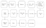
| 4 | Fine sealing mechanism | 1. The upper head structure is composed of a single cylinder, a double guide pillar, two mounting seats, a heat insulation block, a heating element, and a head.
2. The lower head structure is composed of a single cylinder, a double guide pillar, a mounting seat, a heat insulation block, a heating element, and a head. 3. The auxiliary pressing plate, the positioning push plate structure and the battery table plate are the battery positioning functions. 4. During encapsulation, the waste liquid can flow through the stainless steel slide table into the waste box. |
| 5 | Cutting air bag mechanism
|
1. The upper and lower cutting knives are made of SKD11 tungsten steel cutting knives.
2. The upper cutter structure has a simultaneous action of the press plate, and the battery is freely pressed by the way of spring (the press plate is pressed first). 3. The cut off packaging material falls into the residual material collection bin from the discharge port. There is a box in the residual material collection bin that can be taken and placed.
|
| 6 | Edge voltage test mechanism | 1. The cylinder drives the flat-head brass probe to compress the positive and negative electrodes of the tabs, and the bayonet punctures the cell shell, so as to realize the test of the side voltage.
2. Position moving platform: the cylinder moves forward to the receiving position, waiting for the cell of the air bag cutting station to be carried to the cell platform, and then the cylinder retreats backward to the waiting position and the handling mechanism 1 arrives at the waiting position, and the side voltage test can be carried out.
|
| 7 | Cutting and folding mechanism (double folding) | 1. After the cell arrives at the positioning platform, the micro-pressure battery under the low air pressure of the structure is compressed, and the two positioning cylinders act in opposite directions, and the positioning of the battery cell is completed. The hold-down mechanism pressurizes and presses the cell again, the two positioning cylinders are returned and the slide cylinder is depressurized, and the transmission structure drives the hold-down mechanism and the positioning platform to drive the cell to cut the edge first and then fold the edge at the same time.
2. After the cutting and folding action is completed, the compression mechanism rises and the slide cylinder drives the return, the carrying mechanism 2 takes away the battery, and the transmission mechanism drives the positioning platform to return to the receiving position.
|
| 8 | Ironing mechanism | 1. The cylinder drives the pressure plate to stabilize the battery core and press the edge sealing head to press down, so that the two sealing edges are flat on both sides of the battery core.
2. The cylinder of the slide table makes the edge of the battery core flat. 3. There is a heating mechanism of the heating pipe, and the temperature controller controls the ironing temperature.
|
| 9 | Weighing mechanism | After the cell is placed on the weighing platform, the cylinder is lowered, and the weighing platform is automatically connected with the fixture on the electronic scale to start weighing.
|
| 10 | Blanking mechanism | 1. After weighing, OK products and NG products are automatically sorted and placed by the robot.
2. When the conveyor belt product is full, it will give an alarm and take the product manually.
|
| 11 | Handling mechanism | The handling mechanism is divided into two groups. Each group is composed of a combination of the X-axis of the module and the suction cup structure. |
| 12 | Interactive | The touch screen is used to realize the human-machine dialogue and the monitoring of each operation. |
| 13 | Control system | The PLC is used as the control core to control the action of the whole machine, the cell tray code is associated with the cell virtual code, and the information such as NG and rework is associated and tracked through the Ethernet and MES docking. |
| 14 | Fixed frame | Fangtong welding is used to make the performance of the whole machine stable during operation. |
| 15 | Dust-proof cover | The outer cover is made of aluminum profile, and the transparent acrylic is protected. |
You must be logged in to post a review.
No PDF available for this product.


Reviews
Clear filtersThere are no reviews yet.